throttle position sensor wiring diagram
Illuminated Check Engine Light. VW Car Manuals PDF Wiring Diagrams Volkswagen Fault Codes DTC.

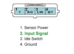
Kia Amanti Questions Can Anyone Tell Show Me The Wiring Diagram For The 4 Pin Tps Cargurus
The wiring diagram for a cruise control system may be included in ACCESSORIES EQUIPMENT section for the specific vehicle manufacturer and the wiring diagram for an anti-lock brake system may be included in BRAKES and WIRING DIAGRAMS for the specific manufacturer.

. Dont start your car. In some rare cases a bad sensor may show higher readings. A throttle position sensor operating outside of a predetermined range can trigger code P0121.
When the knock sensor detects a knocking noise it sends a signal to the ECU engine control unit to adjust the fuel injection and ignition timing accordingly. The throttle position sensor enables. The throttle position sensor has the two sensors.
1tr fan belt diagram. Crankshaft Position Sensor Symptoms. Proportional dosing solenoid valve.
Signs of Bad U-Joints. The knock sensor has two wires one for the signal and one for the ground. Diesel high pressure regulator.
Mercedes-Benz utilizes a drive-by-wire system. Brand new throttle position sensor for 1987 - 2004 honda and acura The Throttle Position Sensor TPS is used to send input signals to the ECU to indicate the current. Shops perform a honda throttle body reset with a scan tool but you can do it manually by following this procedure.
Some of the most common bad crankshaft position sensor symptoms include. Defective Throttle Position Sensor TPS Dirt build up in throttle body. OBD-II Trouble Codes toggle close obd.
Object lesson for temptation. 9 Mar 19 2011. 2020 freightliner fuse box diagram.
With Throttle Position Sensor P0340 and P0345 Camshaft Sensor check. 8 Pin Throttle Position Sensor Wiring Diagram. Type have three connection wires.
High temperature sensor exhaust gas. Diesel high pressure sensor. A faulty gas pedal also known as travel sensor gas accelerator pedal position sensor may develop similar symptoms as a bad throttle position sensor.
Mass Air Flow Sensor Wiring Diagram Mass Air Flow Sensor. The throttle position sensor responds to the throttle valve movement. As you may expect the specific location of the camshaft position sensor varies by a vehicles make and model.
I am posting again the diagram of the eight-pin wiring diagram. Torque Converter Clutch. Diesel pump lever position sensor.
That pot is part of the throttle control. 500 ohms moving to 900015000 Ohms as. These sensors are a kind of potentiometers which transform the throttle valve position into output voltage and emit the voltage signal to the Engine Control Module In addition these sensors detect the opening and closing.
Non-Step Style - If you look inside the connector on the Camshaft Position Sensor. Also if disconnected from the controller. Columbia city accident reports.
The wiring diagram of the mass air flow MAF sensor is different according to the year make and model. How to fix it. Will output 0vdc to 5vdc and the hall sensor will output 8vdc to 43vdc.
Disconnect the pedal sensor wiring harness. 900015000 Ohms across terminals A and C. Fixed the throttle position sensor code.
So a 6-pin accelerator pedal position sensor wiring diagram consists of two ground wires two wiring lines for the input voltage and two signal lines returning to an ECU computer. Look around the top section of the timing beltchain cover in the front of the engine or at the rear end of the. The throttle position sensor is an integral part of the vehicle engine management system located in or on the throttle body assembly.
It sends the reading to the car computer ECU which adjusts the amount of fuel injection into the combustion chamber. The engine coolant temperature ECT sensor is a resistor-based sensor which measures the temperature of the engines coolant. Both the hall sensor throttle and the Pot.
It has two wires for the motor two are signal two are earth and two are hot wires. Symptoms of a Bad Crankshaft Position Sensor. I unplugged my throttle body and removed it from the motor.
2 Wire Knock Sensor Wiring Diagram 2 Wire Knock Sensor Wiring Diagram. The eight-wire electronic throttle body wiring diagram is the same covered in the eight-pin throttle position sensor wiring diagram. Remove the two T30 Torx screws from the accelerator pedal.
The end of the Nissan throttle cable that slips onto the throttle wheel fits in the. Refurbished propane tanks for sale in. CaMshaft Position sensor - Step Style or Non Step Style.
Of course different engines will have different readings. In this powerful guide we will be more general than specific. Nissan wiring diagram pickup 1995 fuse bluebird engine where 240sx hazard lights pick 1989 questions d21 diagrams.
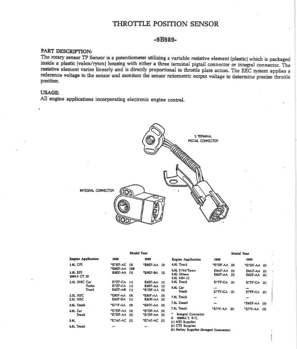
Throttle Position TP Sensor. The manufacturer designs the wiring diagram of the mass air flow sensor according to the need and demand. Two Wire Sensor Working Principle and AnimationSensors can also be broken down by their wiring configurationsThe most common are 2-wire and 3-wireTwo-wire devices are designed to wire in series with the loadIn a 3-wire configuration two of the three leads supply power while the third switches the load.
You might be able to reset the throttle sensor turn key to on position and pump pedal 4-5 time from 0 -100 then back off and then start engine. On most models you can find the sensor somewhere around the cylinder head. If connected to a 5vdc power source and reading the sensor outputs.
A wheel-speed sensor consists of a silicon integrated circuit in the. Mass Air Flow Sensor Wiring Diagram - Exatininfo exatin. Dirty Engine Air Filter.
First throttle position sensor measures the angle of the throttle valve while accelerator pedal sensor measures the pedal depression angle. First try throttle reset. Diagnostic trouble code DTC P2135 stands for ThrottlePedal Position Sensor Switch AB Voltage Correlation This code appears when your cars primary computer which is often referred to as the powertrain control.
Diagnostic trouble code DTC P2138 stands for ThrottlePedal Position SensorSwitch DE Voltage Correlation It is triggered when the vehicles engine control module ECM or powertrain control module PCM detects that the signals from the two throttle position sensors or two accelerator pedal position sensors do not correlate. Redblue wire is energized when the ignition switch is held in the start position. For the non-step style plug socket the hole is the same size in the front of the plug socket as it is at the back bottomed out in the.
Often mass air flow sensor readings are measured at idle 1000 RPM 2000 RPM and 3000 RPM. 1 switch the ignition key to the run position for 2 seconds. Camshaft Position Sensor Location.
What Does the P2135 Code Mean. A good throttle position sensor should have resistance of. The throttle position sensor is located on the throttle body and once it fails code P2135 may get triggered.
You are looking at the socket female side of a quick connect plug. 2 Start the engine and run it at 3000 rpm until the fans of the radiator turn on. The Ford engine belt tensioner has an.
How to Replace a Cabin Air Filter. Because the CKP sensor is a primary input to the PCM the sensor can cause a range of different problems when it fails. 2007 chevy trailblazer camshaft position sensor location.
The PCM monitors the CKP sensor and its circuit. A contaminated or bad air flow sensor will in most cases show lower air flow readings than a known good one. Engine management control unit.
Here is a video on how to test a throttle position sensor with a basic multimeter I also show you how to do this without a wiring diagramMultimeter used in. The ECT sensor comes in different wiring diagrams and colors depending upon the car. With the throttle actuated closed to Wide Open Position.
3 Then leave the end idle for five minutes with no loads.

I Need Help With My Throttle Position Sensor For My 1990 3vze Yotatech Forums
Bimmerforums The Ultimate Bmw Forum

Throttle Body Wiring Jeep Patriot Forums

How To Test The Throttle Position Sensor 3 0l Mitsubishi Montero Automotive Repair Shop Automotive Electrical Alternator Working

Mustang Throttle Position Sensor

6 Wire Throttle Position Sensor Tps 12 Connector Pigtail Wiring Ls1 Ls6

Rb26 Tps Switch Throttle Position Sensor Connector Wiring Specialties

Throttle Body Position Sensor Wiring Diagram Needed
P0122 P0123 P0222 P0223

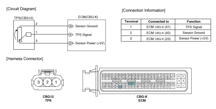
Hyundai Elantra Throttle Position Sensor Tps Schematic Diagrams Engine Control System Engine Control Fuel System Hyundai Elantra Hd 2006 2010 Service Manual

1jz Vvti Tps Throttle Position Sensor Connector Wiring Specialties

Need To Find A 4 Pin Throttle Position For My 2005 E 150 Cargo Van Motocraft Vin Search And Everywhere Else Only
3 Way Mikuni Carb Tps Throttle Position Sensor Wiring Connector

Tps Throttle Position Sensor Freeautomechanic

Throttle Position Sensor Spitronics Support
Throttle Position Sensor Wiring Diagram 08 Int Prostar Isx Cummins Me And A Mechanic New Sensor And Checking With

Toyota Corolla Repair Manual Circuit Description Throttle Pedal Position Sensor Switch A Circuit Sfi System Diagnostics